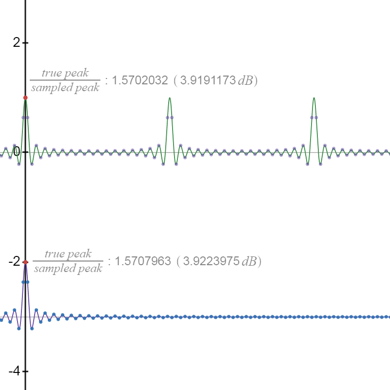
Reconstructed PCM data can have peaks larger than any of the PCM samples. Here are two examples: the sinc and periodic sinc functions:
Inter-sample peaks using the sinc or psinc functions above are limited to pi/2 or 3.9 dBTP.
To construct a PCM wave with larger intersample peaks, notice that sampling a square wave (without antialiasing filtering) results in intersample peaks. Here is an example:

To maximize the inter-sample peaks, sample the square wave at a frequency one harmonic less than the Nyquist frequency. For example:

Notice the spectrum. It's reversed from the normal square wave spectrum. That's because every frequency other than the fundamental is above the Nyquist, resulting in an alias of that frequency reflected across the Nyquist limit. When this situation is present, the wave can be built of cosine components with no phase angle. That is, all the cosine peaks line up. That means the true peak can be calculated easily by adding the magnitudes of each cosine component as found by DFT.
The calculator app does just that, at least for small values of N and f. It does a single-threaded DFT to find cosine components, so performance is too low for large values.
Some periodic wave files using this technique can be found in PerfectSineWaves version 1.3 (generation batch files are in directory demo\bitperfect\intersamplePeak).
The files ending in -over have maximum peaks. Unlike all other files in the archive, these files have peaks that exceed 0 dBTP. For example, file ISP-N_1024K-over.wav has amplitude +19.4 dBTP.
The files ending in -phaseA have maximum peak of 0 dBTP. These files are just amplitude-reduced versions of the -over files.
The files ending in -phaseB also have maximum peak of 0 dBTP. These files have the exact same cosine components as the other two files, but the PCM sampling point is shifted by half a bit time. This causes the PCM sampling to hit the peaks dead-center. In the first two cases, the peaks fall exactly half way between two PCM samples.
The -phaseA and -phaseB files reconstruct exactly the same periodic wave. Both the magnitude and phases of the cosine components are the same. The only difference is a time shift of 1/2 a PCM sample. Being periodic, that means ideally there should be no measurable difference when the two are reconstructed.